![[Home]](/img/mcx_wiki_banner.png)
Frequently Asked Questions about MCX
- 1. What is the easiest way to install MCX on Windows?
- 2. How does MCX capture detected photons?
- 3. I am getting a "kernel launch timed-out" error, what is that?
- 4. When should I use the atomic version of MCX?
- 5. How do I interpret MCX's output data?
- 6. Does MCX support multiple GPUs in a single computer?
- 7. Will you consider porting MCX to MPI to run on my cluster?
- 8. What is the maximum number of media types that MCX can handle?
- 9. What is the maximum number of detectors in MCX?
- 10. My simulation created an empty history file, why is that?
1. What is the easiest way to install MCX on Windows?
Use the following winget command on Windows 10 or newer
winget install mcxstudio
This automatically installs the latest full MCX Suite (which includes everything), including
mcx/mcxcl/mmc executables (and add the installation path to your
PATH env variable automatically), mcxlab/mcxlabcl/mmclab for your MATLAB
(and addpath to all of them), mcxlabcl/mmclab for GNU Octave,
iso2mesh and redbird toolbox for MATLAB, and MCXStudio graphical user
interface (GUI). In addition, it also modifies the TdrDelay registry
key to avoid the NVIDIA graphics driver induced maximum runtime limit
(known as the "watchdog timer limit"), see this FAQ item.
2. How does MCX capture detected photons?
This was explained in details in this github issue reply
https://github.com/fangq/mcx/issues/102#issuecomment-682093350
The full response is copied below:
there are currently 3 ways to capture photons in mcx/mcxcl
1. using a detector (cfg.detpos = [dx, dy, dz, Rd], use cfg.savedetflag to decide what data to store). A photon is captured by a detector only if both of the below conditions are met: 1) they are trying to escape from the domain (any non-zero voxel) to the background (zero-valued voxel or outside of the bounding box), and 2) the exit position is within a sphere (radius Rd) centered at the nearest detector.
you can see that these two conditions restrict that a captured photon must be located on the bounding box/an interface between zero and non-zero voxels, truncated by a sphere centered at a given detector.
if the above conditions are met, a photon will be captured, regardless of their propagation direction. you can, however, set cfg.issaveexit=1 or append letters 'xv' in cfg.savedetflag to store the exit position detpt.p and exit direction vector detpt.v. If your actual physical detector has an NA that limits the incident photon angles, you can then use detp.{p,v} to figure out if it will be detected by your camera/optics in a post processing.
to show what this means, here is the plot of the detected photon positions when a series of detectors is placed on a curved volume, you can see that they are limited to the voxel boundaries.

2. in the latest github version of mcx/mcxcl, I added a new way to detect photons on the bounding box. One can set digits 7-12 in the cfg.bc='______000000' input to ask mcx to capture all photons escaping from the 6 bounding box facets: x=0,y=0,z=0,x=Nx, y=Ny, z=Nz planes, respectively according to the orders of the letters - a letter '1' indicates that you want to capture all photons escaping from that plane, a letter '0' - do not capture. This way, you can define a rectangle-shaped detector but only on the bounding box.the output data are similar to a spherical detector, where you can use cfg.savedetflag to get various info, including exit position and angle. More details, please see
https://github.com/fangq/mcx/blob/master/README.txt#L244-L250
you can also run this sample script to get a demo: https://github.com/fangq/mcx/blob/master/mcxlab/examples/demo_bc_det.m

3. you can use cfg.issaveref to **accumulate** total diffuse reflectance within zero-valued voxels immediately adjacent to a non-zero valued voxel. This gives you the distribution of light **leaking** from the entire surface of the object, as long as you pad a layer of zeros around the object. This accumulated surface light distribution does not store individually detected photon information, instead, their final weight are summed together regardless of their escaping directions. This is more memory efficient, but does not provide the granularity if you want to individually process the detected photon.
Lastly, I want to highlight that both mcx and mmc have the capability of modeling wide-field detectors (i.e. non contact), as long as you discretize the space between the detector and the domain and include that as part of your volume (in mcx) or mesh (in mmc). An example of this can be seen for mmc in Fig. 7 of our [wide-field mmc paper](https://www.osapublishing.org/boe/abstract.cfm?uri=boe-7-1-171) - a rectangular detector can be placed outside of the object as long as you tessellate the gap between them.

Please be aware that any empty space between your widefield source/detector in mcx/mcxcl, if they are rasterized, must be labeled as a non-zero label with an optical property of air, instead of setting it to zero-valued voxel. This is because zero-valued voxels are special in mcx/mcxcl as the background, as I mentioned above, a photon moving from a non-zero voxel to a zero-voxel will be terminated, so they won't make it to the wide-field detector.
let me know if these addressed your questions.
3. I am getting a "kernel launch timed-out" error, what is that?
Answer: This error now shows as "unspecified error" on later versions of CUDA libraries.
This error happens only when you are using a non-dedicated GPU. A non-dedicated GPU refers to a graphics card that is used both for display and GPU computation. Because you connect your display to the card, the NVIDIA graphics driver imposes a time limit on the response time of a kernel (a function running on a GPU). This time limit is referred to as the "driver watch-dog time limit". For Linux, this limit is usually about 10 seconds; for Windows, this limit is about 2 seconds. When a kernel runs on a GPU for longer than this limit, the driver will kill the kernel for safety purposes.
If you have only one graphics card on your system and you have to use it in a non-dedicated way (i.e., connected to your monitor and for MCX simulations), MCX allows you to slice the entire simulation into chunks, so that the runtime for each chunk can be smaller than the watch-dog time limit. This is done by setting the "-r" (repetition) parameter.
For Linux/Mac, if you have a dual-GPU graphics card, you can simply run MCX without worrying about this limit, because MCX automatically selects the second GPU to perform the simulation, which is often not connected to a monitor (if this guess is wrong, you can use -G to manually select the dedicated GPU). Alternatively, if you can install a second graphics card in your machine and connect your display to one of the cards (the weaker one), this will make the other card a dedicated CUDA device. Unfortunately, on Windows, as long as you connect the monitor to one of the graphics cards, this time limit is activated for all GPUs.
For Windows users, you may modify the TdrDelay value in the registry to effectively extend this time-out limit. You can find more info in this thread. You may open File Explorer and browse to the mcx/setup/win64 folder, right-click on the file "apply_timeout_registry_fix.bat" and select "Run as administrator". You should see a command line window that reports success. Then you must perform a reboot before this setting becomes activated. If you use MCXStudio, please follow this video tutorial (Lesson 6) to apply a registry fix to enable MCX to run for more than 5 seconds on your computer. This is important!
For Linux/Unix users, you can kill the X Window System and run MCX in pure console mode (you may boot into "text" mode, or if you are already in graphics mode, you may stop it from a terminal). After killing the graphics interface, you may run MCX on a non-dedicated GPU without the watch-dog limit.
4. When should I use the atomic version of MCX?
Answer: In an MCX Monte Carlo simulation, we need to save photon weights to the global memory from many parallel threads. This may cause problems when multiple threads write to the same global memory address at the same time, which we refer to as a race condition. To avoid race conditions, CUDA provides a set of "atomic" operations, where the read-compute-write process in a thread cannot be interrupted by other threads.
In the first generation of CUDA devices made around 2008, there was a significant speed penalty for using these functions. As we have shown in Fig. 7 in our original MCX paper, the atomic version of MCX could only achieve about 75x acceleration at an optimal thread number around 500-1000, compared with 300x acceleration with the non-atomic version.
Fortunately, the high overhead in atomic operations was fixed in all NVIDIA GPUs made after 2010 (Fermi). Since 2013, we have enabled these atomic operations by default without slowing down the simulations.
5. How do I interpret MCX's output data?
Please read the output interpretation of MMC (Mesh-based Monte Carlo). The meanings of the outputs from both software packages are almost identical. The only difference is that MCX saves the output on a voxelated grid, and MMC saves on a mesh.
6. Does MCX support multiple GPUs in a single computer?
Answer: Yes, this feature has been supported since MCX v2016.4.
7. Will you consider porting MCX to MPI to run on my cluster?
Answer: There are simple alternatives, and you can find my arguments on this at this link. The support for distributed systems is similar to the support for multiple GPUs in the same box. You are recommended to use GNU Parallel to manage parallel jobs. Examples can be found here.
8. What is the maximum number of media types that MCX can handle?
Answer: Since MCX v2019.4, MCX supports continuously varying media, where a user can specify the optical properties for every voxel in the volume, depending on the format. Please see the --mediabyte flag or cfg.vol input format for mcxlab.
For all MCX releases made after 2017, a label-based volume is supported, with the limit that the total number of tissue types plus the total number of detectors must be less than 4000, limited by the size of the constant memory on an NVIDIA GPU.
For MCX releases made before 2017, the maximum number of tissue types is 128.
9. What is the maximum number of detectors in MCX?
Answer: For all MCX releases made after 2017, the total number of tissue types plus the total number of detectors must be less than 4000, limited by the size of the constant memory on an NVIDIA GPU.
For example, if one uses a volume containing 5 tissue types, the maximum detector number is 4000-5=3995.
10. My simulation created an empty history file, why is that?
Answer: This is typically caused by detector position offset due to an incorrectly assumed coordinate system origin.
In MCX, the default coordinate system is the MATLAB volume index (in {x,y,z} float triplet, all starting from 1.0). As a result, the origin of the volume (the corner of the diagonal direction of the first voxel) is (1,1,1) instead of (0,0,0). If you want to use (0,0,0) as the origin, you can do so by adding "--srcfrom0 1" to the command line. The following two figures (the bottom face of an 8x8x8 volume) show the differences between these two options:
| default or --srcfrom0 0 | --srcfrom0 1 |
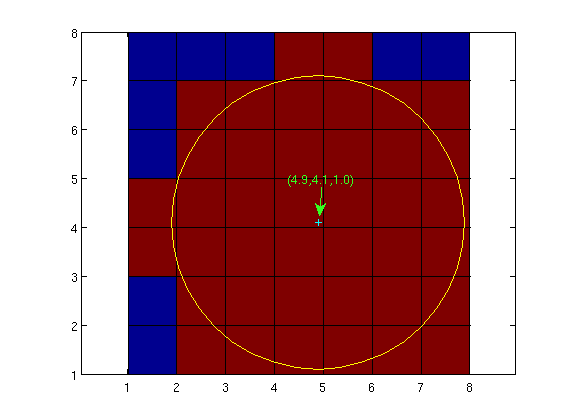 | 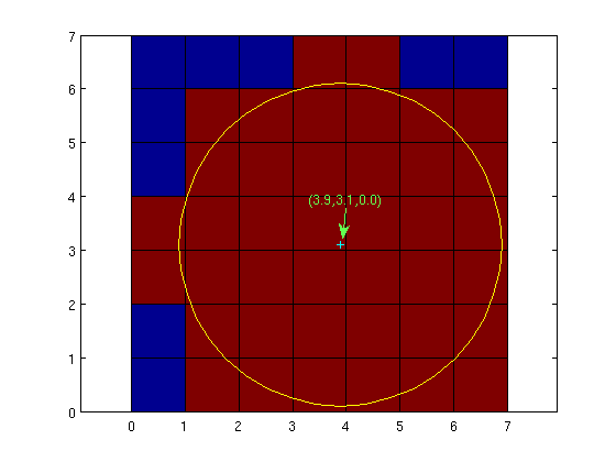 |
You can find more discussion here:
http://groups.google.com/group/mcx-users/browse_thread/thread/e5e0140d7e73e4bf?hl=en
A photon detection event only happens when a photon escapes from the target to the exterior space. This includes two situations:
- a photon moving from a non-zero voxel to a 0-voxel
- a photon moving beyond the bounding box of the volume
Thus, in order for a detector to capture an escaped photon, it MUST be located on the interface between the zero/non-zero voxels, or on the bounding box (within the detector radius). This makes it very sensitive to the coordinate origin issue above when the detector radius is 1mm or less, because if you mistakenly offset your detector by 1mm, the detector will capture nothing, thus giving you an empty history file.
To help with better use of this feature, starting from MCX 0.5.2, we allow users to specify coordinate origin types in the input file. The 3rd row of an input file now accommodates a 4th input, specifying the srcfrom0 flag. For example
30.0 30.0 0.0 1sets the srcfrom0 flag to 1 (the last integer). As a result, the volume origin is set to (0,0,0). This is equivalent to
31.0 31.0 1.0 0or
31.0 31.0 1.0This setting will be effective for both source and detector positions.